Building her
Building 1985–6
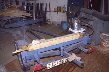
Strongback ready for deck building.
First layer – 3 mm thick plywood – of a deck.
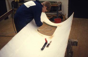
Second layer – 4 mm thick obeche veneer – being trimmed to fit.
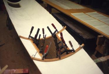
Obeche veneer being vacuum-bagged in place.
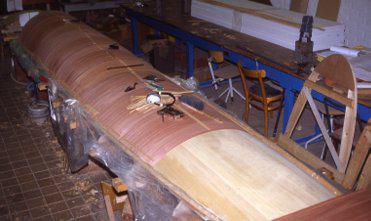
Fitting the outer layer of the deck. This is 1.5 mm mahogany veneer.
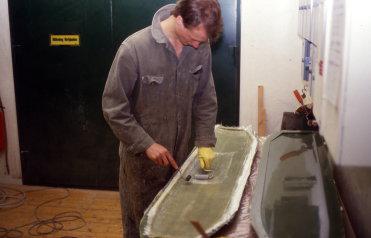
Spreading thickened epoxy.
Staples and vacuum bagging to hold down the outer veneer while the epoxy cures. The vacuum is generated by a slaughtered vacuum cleaner. Hence, not much vacuum but leak tolerant.
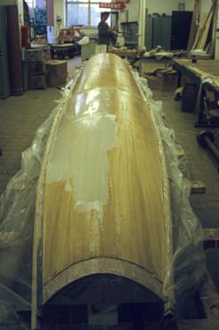
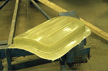
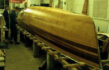
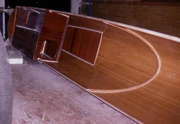
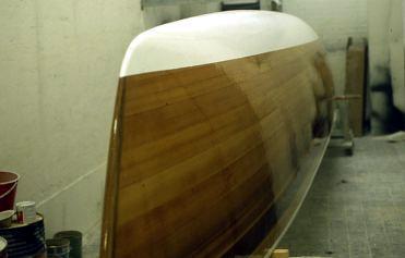
Moulded deck with one coat of clear epoxy. It looks good but had we known how convenient strip-planking is, we would never have gone for cold-moulding. Malcolm Tennant's plans specifies strip-planking for decks and hulls. I do not remember why we opted for cold-moulding.
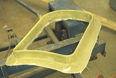
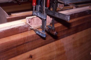
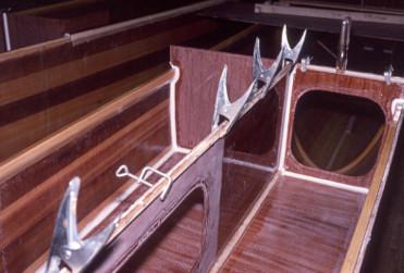
Deck hatch coaming. We borrowed moulds for this and the hatches from a friend who had built a 39' cat with rounded decks. There was a difference in deck radius, so we cut away the flange of the coaming before bonding it to the deck.
Raw deck hatch on coaming.
Hatch coaming being installed in a deck. The inside of the deck has been coated with epoxy mixed with titanium oxide pigment.
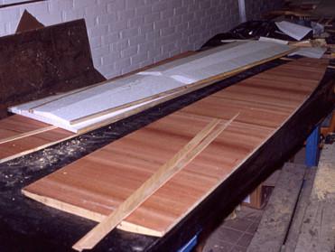
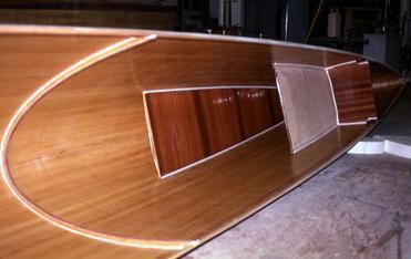
Preparing the deck for a fore-deck hatch. Glass fibre cloth for a rudder ready in the background.
Here we are steaming some wood pieces we wanted to bend to a tight radius.
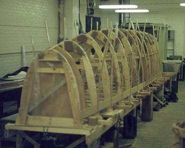
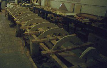
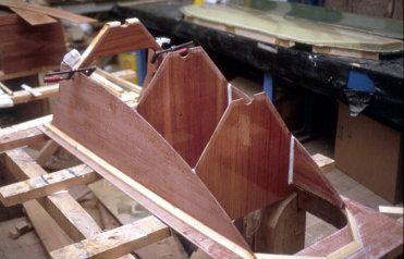
Now the strongback has been converted to hull building. Transom, internal stem and one gunwale plank in place.
A hull is starting to take shape. The 8 mm thick cedar strips are glued to each other, the transom, and the internal stem while being nailed to the frames. The glue was a home-made mix of epoxy and saw dust. The strips are just straight strips with square sides. The width varies to make it easier for them to follow the curvature of the frames.
Adding sawdust-thickened epoxy to three or four wood strips in one go.
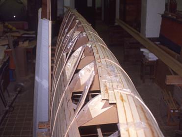
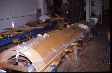
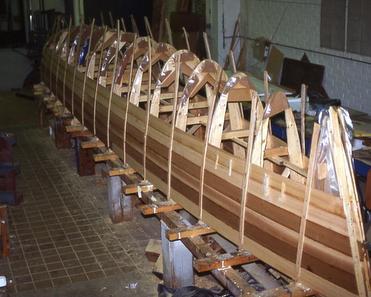
This is how far one gets in day one of building a hull shell. One side of the hull is fully planked. The other side almost fully planked. The reason for the difference is the fact that the planks from side one must run beyond the centreline at the keel.
What it looked like from the other side.
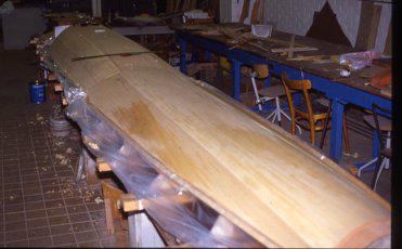
Day two has been spent trimming down the excess planking of side one at the keel and adding the last planks of side two. Bunk bottoms are being prefabricated on the workbench to the left.
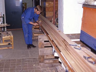
Some hand planing and machine sanding also belongs to day two.
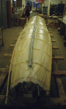
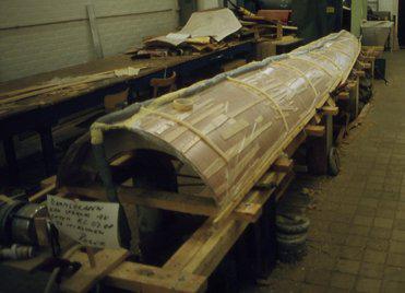
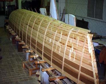
This picture shows the final work of day three: glassing the outside of the hull shell. Since the glass cloth is unidirectional, there is no need for overlap along its sides. The wood fibres are the only load carriers in that direction anyway.
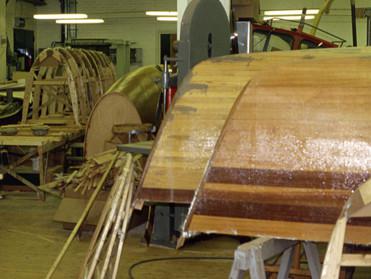
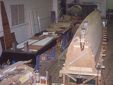
A hull-littered workshop. We are done with the strongback, so it is being cleared.
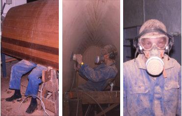
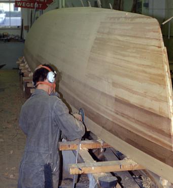
Sanding the inside of the hulls was both exceptionally noisy and dusty. After a few hours, one felt a bit fuzzy.
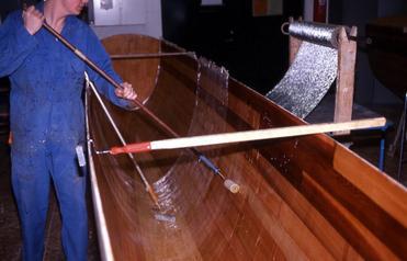
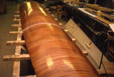
Time for glassing the inside of the hull with the same type of unidirectional glass that was used on the outside. Just before this step, each shell weighed 70–75 kg.
Adding UDWR glass for spreading loads at the rear beam attachment.
Sandwich bunk bottoms: Styrofoam, wood veneers, stringers, and GRP. The glass laminate had not been added when this photo was shot. We used a lightweight – 155 g/sqm – glass cloth for the bunks.
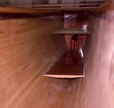
This photo shows the forward bunk meeting the forward bulkhead. All interior parts were prefabricated, including epoxy coating all surfaces. We could make all parts fit accurately by using measurements from the mould frames. Only minor trimming at the gunwales was needed. This photo shows a dry run with the forward bunk, forward bulkhead and the floor of the foredeck stow.
All parts were bonded to the hulls using home-made epoxy bog (epoxy + Q-cell micro balloons).
The cockpits were also assembled from prefabricated parts. All epoxy coating was done prior to assembly. Being able to coat all surfaces before assembly is central to this building technique and it results in a low-maintenance wooden boat. Quality control is much easier on a workbench than inside a hull.
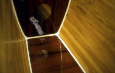
These two photos show the almost complete basic interior of a Spyder hull.
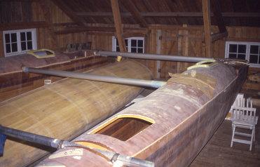
Aligning hulls and cross-beams after decks and hulls had been bonded to each other. This phase of the project did not take place in the workshop where we built the hulls but in a farm building.
Laminating UDWR glass for main beam sleeve.
Heavy UDWR glass to spread loads at dagger board case exit.
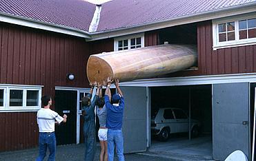
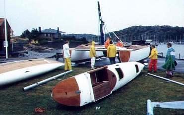
Extracting a hull from the up-stairs alignment workshop in spring 1986.
Carbon pre-preg does not have looks like this.
Laminating a rudder.
Engine nacelle under construction. 4 mm plywood was used.
Launch July 20, 1986
First assembly on the lawn of GKF.
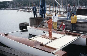
Afloat! Sailing is still about a week's worth of work away.
New crossbeams 1988–9
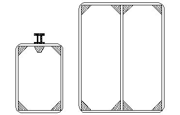
Cross-sections of the new cross-beams. The mast beam is 35 cm deep. Materials are 6–7 mm birch plywood oriented with the veneers at ±45° to maximize shear stiffness. Spruce stringers and some UDWR glass are used to improve bending characteristics. These materials were deemed the best choice within my economical flight envelope at the time. Birch plywood and spruce were used for aeroplane construction, and I am not surprised. You need very high-quality glass fibre laminates to beat them. Today, carbon would be a rather obvious alternative.
NB. Local reinforcements and other details are left out of the drawing.
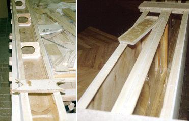
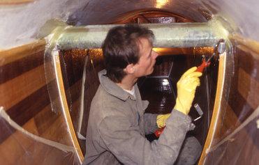
Aft beam and mast beam under construction. Three sides in place. I am working on bulkheads and local reinforcements.
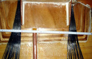
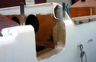
This is a bad shot of the reinforcements where the mast beam end interfaces with the hull. The underside of the beam and the hull sheer line are located at the very top of the photo. The task of the plywood patch is to transfer compression forces into the hull structure. The carbon does the opposite. Carbon replaced glass here after I had some issues in this area. Glass has worked fine everywhere else. I simply did not use enough of it here.
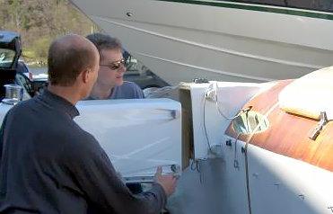
Here is how the mast beam scarf works when we put the boat together. Note that the mating cone is less than 10 cm deep.
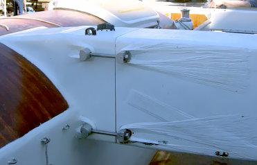
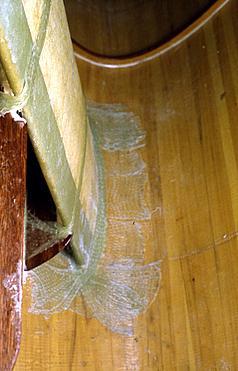
The beam is in place. Bolts are to be tightened. Note the glass that takes the load from the aluminium pieces and spreads it over a large area of the beam.
The aft beam is bolted down in a more conventional manner. These threaded (M12) studs are 'only' bonded to the wood using over-sized holes penetrating almost 20 cm into the wood reinforcement. Unidirectional glass is wrapped over the wood reinforcement on each side of each stud and spread down the in- and outside of the hull.
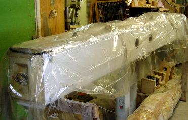
Vacuum bagging unidirectional carbon to the mast beam after having removed the dolphin striker in 2004.