Cross-beams
What forces act on the structure?
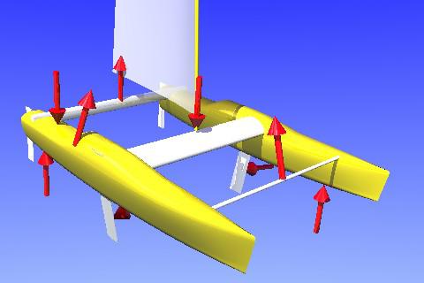
Look at this picture and use your imagination to see the cat hard on the wind in a seaway. The rig is loaded up, but we are not fully flying the windward hull yet. The windward hull has almost passed a wave while the lee bow is digging into that wave. The weight of the boat and crew are supported (mostly) by the lee bow and the windward stern. This induces both bending and torsional loads on the cross-beams.
The mast is held up by the windward shroud, and since the shroud is attached to the windward hull well aft of the main cross-beam it induces a load on the forestay. The shroud and the stay both contribute to the mast compression. The sheets are 'cranked home' and the main sheet tries to bend the middle of the aft beam upwards. The load on the main sheet also contributes to the load on the fore stay and to the mast compression. The mast compression results in a huge bending moment in the middle of the main beam.
The sails drive the boat forward but since we are going to windward most of the force generated by the sails is trying to push the boat sideways. The dagger boards counter this and the result is torsional loads on the hulls and bending of the beam ends.
Analysis and design
Computers have become cheap and powerful, so there are no good reasons left for not doing proper structural engineering. Provided that you have the skills needed; it is not too hard to model a structure like the one above. The hardest part is finding accurate material data.
When it comes to adding loads and analysing the loaded structure, I think it is wise to analyse wave induced loads and wind induced loads separately and then get the total stresses by adding the results. This will lead to a bit of over-engineering, since max wind load means the windward hull flies and will not face the full force of the waves.
It is important to realize that the material stresses should not exceed stress levels that are deemed acceptable for many, many load cycles. Material fatigue is what interests us rather than ultimate breaking strength.
One of the advantages of computer modelling is the possibility to compare several design alternatives with relative ease. I, for one, assumed when we started to investigate this that the bending characteristic of the cross-beams was the most significant factor to study and optimize. Playing with the computer model, we soon learnt that the torsional stiffness also is important.
Guided by our models, we ended up with a design in which the platform is held together by two beams. The torsional stiffness of the main beam is a substantial part of the overall wracking stiffness of the structure. The aft beam matches the main beam's bending strength, since the bending loads at the beam-hull joint are the same for both beams for two-beam cats subjected to wracking loads. The front beam is 'only' a compression member to the seagull striker and the front edge of the trampoline. There are other cross-beam schemes that may be as good or even better, but this was the one we felt suited the existing boat and our needs best.
Real world experience and bench marking
We did not analyse Scarlattikvarten exactly as described above. Computer power was not at today's level in 1989. I have re-visited our analysis since then, and the numbers I produced still look good to me. Most important is of course the fact that I have had no structural problems since 1989.
Some years ago, I came across the structural data for an offshore racing cat design that has a well-established reliability record. I put it through its numerical paces in my computer and found the kind of material stress margins with respect to material fatigue that I would have aimed at myself. This was a very encouraging experience.
Don't try this at home
Unless you know structural engineering.